From the top-level diagram of the engine control unit (ECU) last time, you could see that the ECU actuates a servo, a (brushless) DC motor, reads out sensors and is a big intersection of power and signal lines.
In designing the engine control unit, we first had to check the highest system voltage level in order to decide on the power source. The DC motor, used for actuation of our main valve requires the highest voltage, that is, 24 V nominally. For this reason, we picked a 6-cell LiPo battery that could power the ECU and regulated to power other subsystems like the 12 V sensing circuitry or the 3.3 V logic circuits.
Drawing all the circuits from scratch is quite challenging for students from the Electrical Engineering studies without PCB design experience: not only do the circuits have to technically sound, but the design also must adhere to the functions required and have all interfaces to other PCBs.
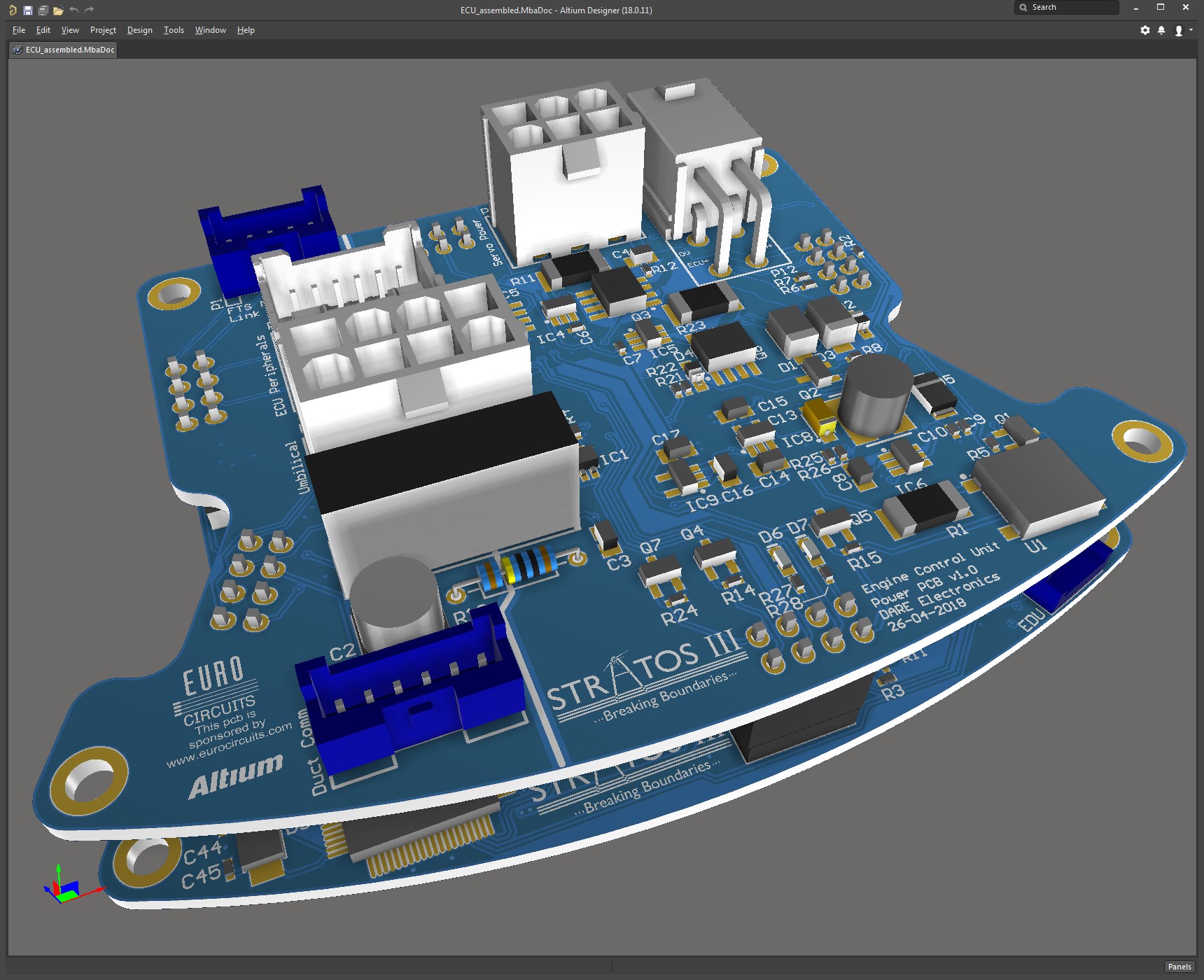
Render of our first ECU design.
Luckily, we can rely on ECU designs from previous teams and we have access to almost all electronics design files within DARE Electronics’ history. This means that certainly a lot of circuits with same functions can be reused and the time getting to routing of the copper can be reduced. With routing, we can still ask for advice and checks from alumni too—they have more experience after all! For these reasons, we were able to have a relatively fast first design of the ECU.
by Hans Okkerman