In this second part of our 2 part series on the engine bay, we’ll be talking about all of the systems that can be found in the engine bay. All of the systems that control the engine are inside here, so there is a lot to see.
In the very middle of the engine bay is the main oxidizer line between the tank and the engine. This has to be controlled by a valve, called the main valve. To control this valve we need an electric motor capable of delivering a large amount of power, but is small enough to fit inside the rocket. This motor is supplied by Faulhaber.
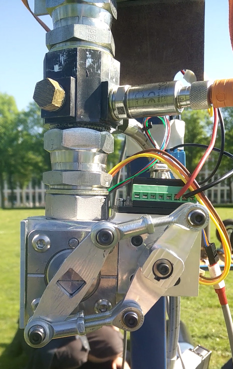
The testing setup for the main valve. The valve is on the left, and the motor on the right. They are connected by a custom transfer mechanism that is lighter and more reliable than a traditional gear based system.
Aside from the motor, there is also the main oxidizer line, plus an additional line and valve for fueling. To supply our oxidizer, nitrous oxide, to the rocket, several additional lines and valves are needed on the ground. When doing tests for the engine, even more valves and lines were needed. Teesing helped us in the design of the feedsystem, which is what all of these valves and lines together are called. They also supplied valves and adapters. Working with all kinds of different diameters and fittings can be very challenging, and Teesing helped us through that process.
All these valves need to be controlled to the electronics of our rocket, so that they can be operated correctly in the countdown and flight. Sensors that measure things like pressure and temperature also need to be hooked up to the electronics system. LEMO supplies connectors that we use to connect the cables of our actuators and sensors during testing and flight. The most important connection is where the umbilical cable connects to the rocket. The umbilical is a cable that connects the rocket to our computers while the rocket is still on the ground. When the rocket is launched, this connection needs to come off, to allow the rocket to take off. While the rocket is still on the ground, it is vital that the connection stays intact.
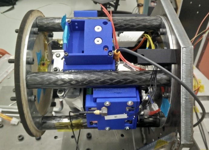
This is what the engine bay looks like once most of the components have been installed. There is not much space left.
Thank you for reading this second part in our series of 2 blog posts on the engine bay. If you missed the first part, be sure to read it as well. It explains the structure of the engine bay, in which all of these components are placed. Be sure to read our posts on other parts of the rocket as well.
by Daan van Heteren