The Small Rocket Project (SRP) is DARE’s project for first-year students. While we do try to advertise it as a fun and exciting process, unfortunately it is not always smooth runnings. One of these problems is the stricter BSA (Binding Study Advice) requirement that cropped up in the past few years, putting students under pressure and making them more conservative with their extracurricular choices. If they think what they’ve taken on is too much, they drop it. As much as we fully understand this choice, we don’t want stop educating them so that they can be fully involved by the second year with the necessary skills. This is one of the primary reasons the electronics team are busy redesigning the SRP electronics that are used to deploy the parachute of these rockets at apogee.
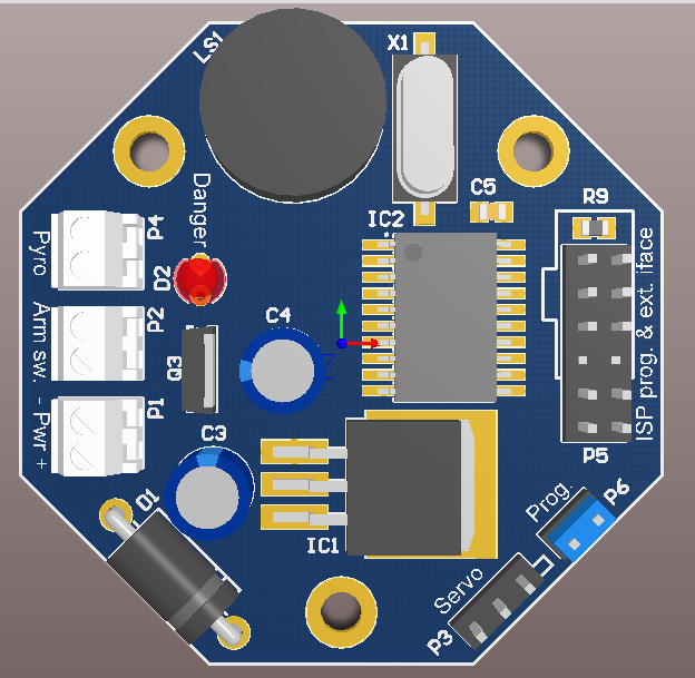
SRP Board Design Render
The old setup consisted of a short introduction, followed by a soldering tutorial, and concluding with the production of the actual board. The board was produced on stripboard with through-hole components. It was difficult for first timers. Patchy understanding of how the board worked coupled with them having to make the layout themselves resulted in very buggy boards of questionable quality that were prone to failure. Doing this in an 8-hour session also proved totally unrealistic: It took several hours more to get it working. One determined member pulled his hair out for two weeks getting his board working (which it eventually did although only to fail at launch).
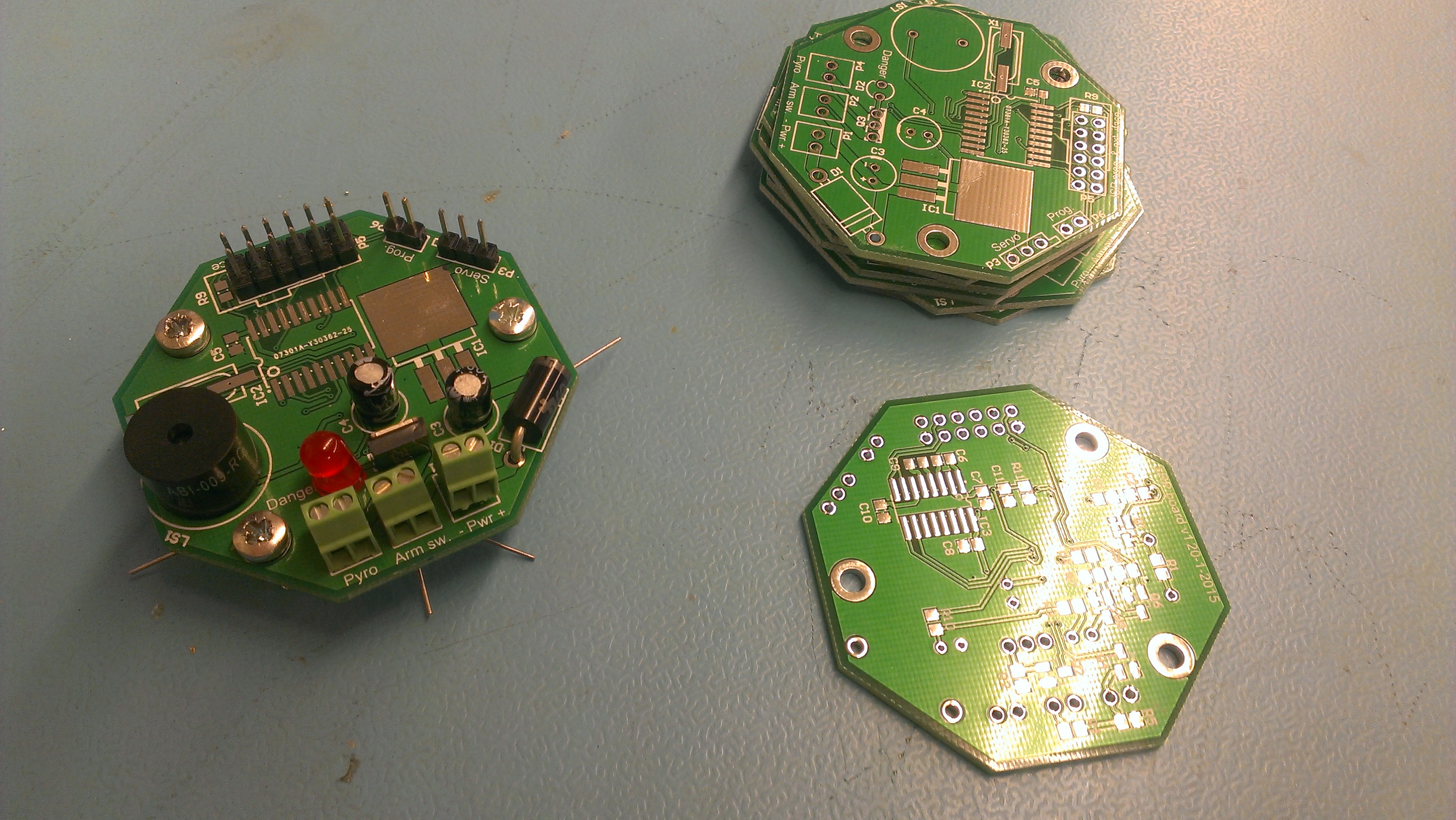
New SRP Electronics Board
The new board is a finished circuit board with a mix of both DIP and SMD parts to teach the two most important solder techniques. Several Updates were made:
- The processor has been upgraded in memory to the Attiny 4313 rather than the 2313 (Increasing the memory from 2kB to 4kB), and is also now in SOIC format (in other words a integrated surface mount component) to save a bit of space.
- It has an octagonal shape (like Stratos II Boards). It fits within the engine diameter, the minimum tube size of the rockets. This means that that it can ride horizontally, permitting the lowest forces on the board. There is no shear on components, but only stress. The flight critical components are positioned on the upper side to be pushed into the board.
- All components positions are beautifully labeled: Everything has a place. We are confident this makes it possible to solder, flash (i.e. program) and test it within two four-hour sessions.
All of this may of course lead to the question: Where is the electrical engineering learning aspect? While working on this, the idea was proposed to create an optional breakout board, in other words an additional, empty stripboard to be mounted on top of the old board. This would allow easy connections to expand the capabilities of a device.
It would however be a lot simpler than the old self-built board: at minimum it would only need a sensor (e.g. for pressure) and a processor to evaluate it and to ‘vote’ when it should deploy the parachute. If it doesn’t work, it can still fly without it. The main board can also still evaluate whether it produces sensible input- i.e. ignore if it is outside a certain timeframe after launch. We hope this will be the platform upon which all sensors and crazy ideas are placed, from accelerometers to flight data recorders.
The SRP launch day will be on the 5th of June. We’ll keep you posted on Facebook and Twitter!