Since some time the DHX-200 Aurora rocket motor for the Stratos II rocket was set ready in the TNO rocket test facility in Rijswijk. This rocket motor that will propel the Stratos II rocket to 50 kilometres altitude of course needs to be tested to make sure that it can perform as expected.

Stratos II is a rocket that is designed and built by students from Delft University of Technology in the Netherlands. The rocket is designed to launch a scientific payload to 50 kilometres altitude. To make sure the mission will succeed all different subsystems need to be tested. Therefore the propulsion segment was tested statically and all important parameters and the performance of the motor were measured.
Stratos II uses a so-called hybrid rocket motor. The rocket motor is comprised out of a combustion chamber containing solid rocket fuel that reacts with the pressurized liquid nitrous oxide that is being injected into the chamber. As fuel a combination of sorbitol, paraffin wax and aluminium particles is used. In combination with pressurized nitrous oxide as oxidiser this novel fuel combination delivers all the required thrust. The DHX-200 Aurora is designed to deliver a total impulse close to 200.000 Ns and a peak thrust of just over 10.000 N. Every second 5 kg of propellant are burned and expelled through the nozzle.
Test 1: 5 seconds burn time
The first test at the facility was performed on 28th May. This was the first time the DHX-200 Aurora motor was fully ignited. The motor was fired for 5 seconds, after which it was shut down in a controlled manner by closing the main oxidiser valve. The DHX-200 Aurora is designed to eventually fire for almost 20 seconds. This first time however, the oxidizer flow was cut off early so that the team could inspect the motor afterwards and evaluate the results.
Test 2: 10 seconds burn time
On Wednesday, 12th of June, the motor was prepared for a second test day. After the first 5 second test fire the burn time of the motor would be increased in steps. The next step was to fire the motor for 10 seconds continuously. It performed beautifully and delivered a good performance.
Test 3: 15 seconds burn time with rupture of the combustion chamber
The logical step after the successful 10 second test was to increase the burn time even further. The third test, which took place on the same Wednesday later during the day, was scheduled to take 15 seconds. After this the oxidizer flow would again be shut down. After about 5 seconds however a crack appeared in the wall of the combustion chamber and the motor was shut down by closing the oxidizer flow immediately, extinguishing the motor safely.
What went wrong?
The rupture of the combustion chamber is something that needs to be prevented. To analyse what went wrong during the test the team started to systematically check all parts of the engine to see what could have been the problem. The suspicion quickly fell on the fuel grain that sits in the combustion chamber. This fuel burns with the oxidizer to generate the thrust of the rocket. The fuel burns from the inside outwards and in that way it also protects the wall of the combustion chamber from the hot combustion gasses. If however the grain contained some production errors, it may not have done its job of protecting the chamber wall.
To analyse this, the team took a fuel grain that was prepared in a similar manner and with a similar technique as the one used during the test, and analysed this with an X-ray computed tomography (CT) scan. This particular fuel grain was not going to be used for a test because it had a clearly visible, large crack in the middle that that had already been observed beforehand. The team however wondered if there were also cracks and bubbles that could not be seen. Using the CT-scanner at TU Delft’s Faculty of Civil Engineering and Geosciences the inside of the grain could be inspected.
This was a grain that was deemed not usable during a test because of the big hole in the middle of the grain that was visible from the outside. The CT-scan however also revealed a number of smaller cracks and air bubbles in the interior of the grain.
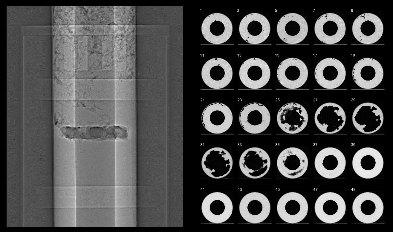
CT-scan cross-section of a DHX-200 Aurora grain (3mm slices)
As can be seen in the picture the grain contained, next to the big hole that could be seen from outside, also a number of smaller bubbles. Next to that parts of the grain appeared more porous than others. The team suspects that one of these bubbles allowed the hot gasses to reach the combustion chamber wall very quickly during the test. This weakened the combustion chamber and caused it to break.
How further?
The first test series at TNO is now completed and the team has learned a lot. The first two tests show that the DHX-200 “Aurora” can perform as intended. Test 3 shows that the employed safety measures function well and that the whole system is safe to work with. It however also shows that the team needs to rethink the production method for the fuel grain and for future tests needs to inspect the grain not only from the outside. For future tests the grains will probably all be inspected by scanning them beforehand. Near the end of the summer the team will continue with the test sequence to test the engine up to its nominal burn time of 20 seconds.
This first test campaign was very promising and very exciting for everyone and we are looking forward to the next opportunity to test the motor.
8 Responses
Dear DARE rocketeers,
I am deeply impressed!
Such great results during the first test campaign.
Professional video and data recordings!
And now a problem which you apparently already understand.
I am sure you will find a way to solve it!
This will be an amazing machine once it is ready.
Please keep up the good work.
You can be proud at your achievements thus far!
I look forward to more good news in the summer.
Kind regards,
Boudewijn Ambrosius
Dear Dawn team,
I fully second Mr. Ambrosius’ comments. It is truly impressive to see the professionalism you have applied for test test.
DARE has made an astonishing progress over the last years in becoming more professional, methodological and above all safe.
Impressive how fast you identified the root cause and how to prevent it the next time. Good luck with improving the grain production methods!
Keep up to good work and stay focused, but do not forget to also take time to step back for a second and enjoy and realize what amazing things you are working on and what you already have achieved.
Peter Batenburg
at 0:29 of the 15s burn test. What is the guy on the right looking at?
Hello Frank
That guy is the Safety Officer from TNO. As soon as he noticed something was going wrong he turned his attention to the guy sitting at the table (he is also from TNO), as this guy has his hand on the kill switch for the engine.
At the moment the Safety Officer turns his head the switch is however already flipped (you can hear the click in the video), this stops the power to a normally closed valve, which then closes and stops the oxidizer flow.
Kind regards,
I have read the very interesting article in the newspaper today, in which a bit of the engine principle is explained. But looking at the videos a few questions come up.
How is the engine ignited? What is happening when the ‘sparks’ are coming out of the engine at the beginning, and what happens in the engine when it is fired to the max?
Kind regards,
Arjan
Hello Arjan
An igniter that is made mostly out of steel wool is placed in the igniter just after the injector. A small explosive squib is placed in the steel wool. This squib is set off at t-3 seconds. At the same time a small bypass valve allows a small amount of N2O to already pass into the chamber and react with the squib and the (now burning) steel wool. This heats up the inside of the chamber. The burning steel wool also creates the sparks you see at the beginning.
At t = 0s the main valve is opened (something you can actually also see happening in the videos when the combustion chamber is seen from behind). The engine ignites now because the burning steel wool has already heated the combustion chamber. If this long heating from the burning igniter was not done, the sudden flow of cold N2O into the chamber would have simply blown out the igniter.
I hope this rather technical story answers your questions? Feel free to ask more if you want to know more 😉
Kind regards,
Rob
Hi Rob, thank you for this answer; well explained!
I do have another question. Behind a rocket engine, or jet engine of a plain, in the flame behind the motor you can see some kind of a wave pattern. like a standing wave. This is also visible in the videos
What is this/how is this caused?
My son, who is also very interested, has also a question. Not about this project, but about the motors of the space shuttle.
When the space shuttle is launched, three engines are fired; the big one in the middle and two aside. The very heavy space shuttle itself is mounted at one side of the rocket. My son thinks that the combination should be very out of balance and the space shuttle should make a curve and not a staight line into space.
Can you explain how this is done? Most rockets are symmetrical and do not have this problem.
Kind regards,
Arjan, also on behalf of my son Roel.
Hello Arjan
First on the standing wave in the exhaust. These forms are called Mach diamonds or shock diamonds. The gasses come out of the engine at high speed and high pressure. These gasses expand in the nozzle (http://projectstratos.nl/2013/03/aurora-motor-production-and-testing-update/) from this high pressure to lower pressure and higher speed. The nozzle is designed for a certain outside air pressure to expand the gasses efficiently to. For the Aurora the gasses would expand to outside air pressure at 3 km altitude. Here at the ground, the pressure seen by the gasses is higher than that and so this pressure creates a shock wave that reflects a number of times in the exhaust, creating the pattern. The exhaust of the Aurora at sea level is called overexpanded
Concerning the space shuttle: What all big rockets such as the space shuttle use is called thrust vector control. This means that they can steer the exhaust of the rocket to make sure they travel in the right direction. Both the Solid Rocket Motors on the side, and the shuttle main engines do this. Furthermore, at launch, the big orange tank is actually also very heavy as it is completely filled with propellants. So the whole combination is not that much out of balance as you might think. And then finally: The space shuttle is flying with a curve to finally get into orbit, try and see the Google Earth projection from here: http://www.nasa.gov/mission_pages/shuttle/shuttlemissions/shuttle_google_earth.html
See you later Arjan, and maybe see your son at Delft University in a number of years? ;p
Rob
Comments are closed.