Remember from an older blog post of mine where I went through the design process of an electrical-mechanical interface and ended with the futuristic-looking, 3D-printed prototype casing? In the meantime, we have been able to design, produce and test the printed circuit board (PCB) that goes on top of it: the bleed valve controller!
The Bleed Valve Controller
After getting the 3D print and noting some of the changes to be made, we fixed the mounting hole’s positions so that we could create the PCB in the PCB design software. Of course, you start with requirements: what do you want it to do (functionalities) and with what specifications/conditions? For the bleed valve controller its main functionalities are actuation of two solenoid valves, being able to relay communication and to communicate by itself.
The requirements were relatively simple, so the PCB’s electrical schematics all fit in one sheet. In a nutshell, it consists of two big transistors to actuate the valves, power circuitry and a microcontroller to talk and control. After finalizing schematics, we took the defined PCB shape and placed the components to draw the copper traces etc. in the design software.
Luckily, just after placing final logos, we caught the mistake of missing some small part of the power circuitry! This shows how important reviews are, it took 4 reviews to notice such a critical mistake.
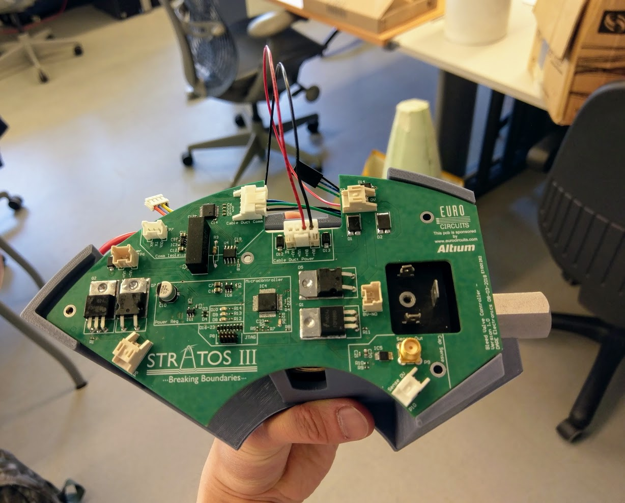
Post-testing, we were quite happy with the result. The software was made ready to have the PCB run its required behavior and only find a few errata for the next version. The PCB fit nicely in the casing!
by Jun Feng