Now that the Data Control Unit is made, work can start on the Telemetry PCB. This board will take data from the DCU and make sure it gets to the ground stations. It also takes the video from two of the on-board cameras and transmits those streams to the ground, after overlaying useful data on top of the video image.
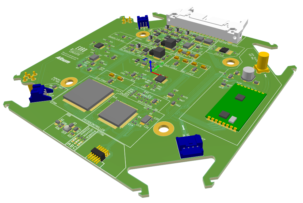
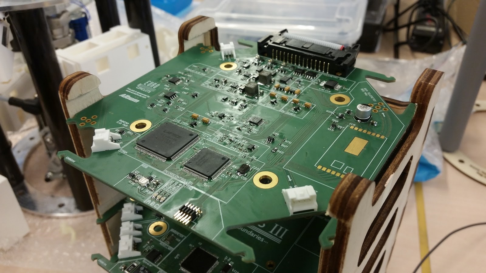
Below you can see images of the Telemetry PCB, compared to the 3D design of the board.
To transmit the data from the DCU, a 915 MHz link was chosen, as it is a frequency for which modules are readily available, and the link will be reliable over a fairly long distance. The board design incorporates another (commercially available) board which modulates the telemetry to this high frequency. After that it is transmitted to the ground, using a helical antenna.
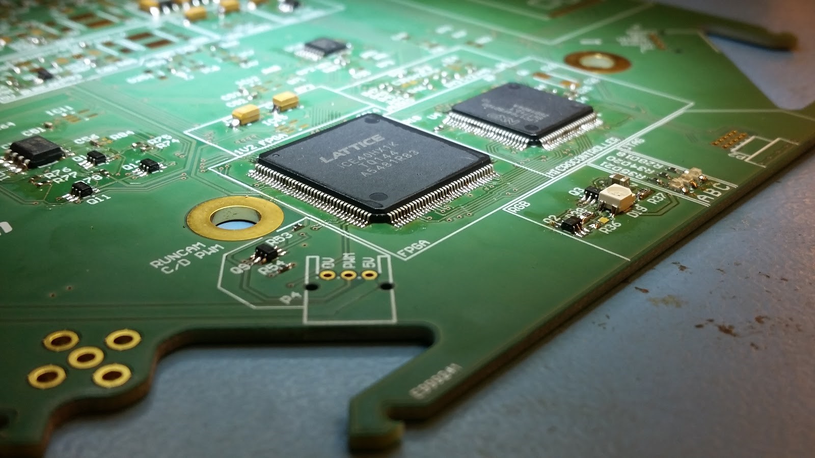
The most complex part of the Telemetry board is the circuit that makes the video overlay. This processing is done on the rocket as a form of redundancy, as the text on the video can still provide data to ground crew, if the data link described above fails for some reason. On top of that, the audio stream of the video link, will be replaced by a data stream.
Hand-soldered integrated circuits, with 0.2mm space between individual pins.
Finally, the four cameras on the rocket have to be controlled. The cameras need to be turned off and on in case there are long wait times on the launch pad because the batteries have limited charge. Next to that, the recordings need to be managed so that the SD cards do not run out of storage. If that happens, we might lose the recording of the flight, which would be quite sad.
by Jillis Noordhoek