After ordering the Recovery Board, I immediately started working on the next thing: The Data Control Unit (DCU). This piece of electronics hardware will also be a part of the flight computer. It will take control over and manage a big part of the data-flow in the flight computer. DCU will also decide on what data is being sent to the telemetry/video board, so it can be relayed to ground stations during the flight of the rocket (more on that in a future post!).
Another important function is that it will send important data to the black-boxes that will be in the rocket. These boxes are better protected against a hard landing of the nose cone in the water, and will improve our chances of recovering valuable data.
Initially a different team member was working on this PCB, when at some point he had to leave to finish his studies. Then, the design files were handed over to me and I had to do the finishing touches. One of my tasks was adding the payload interface, so the rocket can ‘talk’ to the payloads that will fly on Stratos III, and also gather data on their energy usage.
For that, I had to move the microcontroller out of the way, which seems like a simple task, but it is quite time consuming. This is because the microcontroller is the brain of the board, and thus connected to everything. If it needs to be moved, all the connections and components around it should also be moved (quite manually).
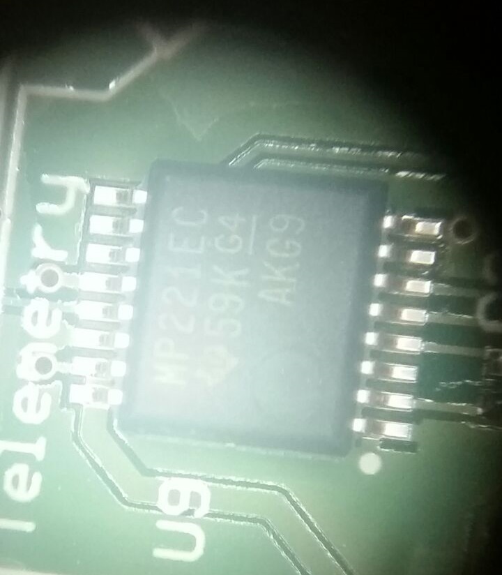
Then we had the board manufactured and started soldering. While soldering the components onto the DCU, we found that one component had the wrong footprint. The footprint is the ‘landing’ area on the PCB that will make the connection between the component leads and the board. In this case, the footprint exactly matched the component. This may sound good but there has to be some extra area where the soldering iron can be put against, to make the connection. The image below shows how the leads of the component are as long as the pads on the footprint.
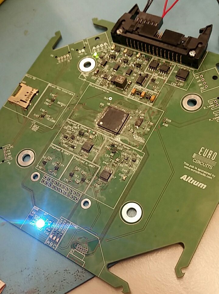
The Data Control Unit.
It was quite tricky to solder, and hard to see whether the tin has made proper contact with the pads. When the board was tested it worked, but we will change the pad length and keep this board as a reserve, it might be too risky to fly with this board in the flight computer. Below, you can see an image of when this board was first powered on.
Powered Data Control Unit.
by Jillis Noordhoek